
Welcome to the JeepSpecs.com in-depth page on the WK Generation Jeep Grand Cherokee tire pressure monitor systems. Did we miss anything? Please get in touch with us and tell us about it!
Two TPM systems are offered for 2005-2010 Grand Cherokees. The base version, included Standard with all Laredo models, consists of tire pressure monitoring sensors attached to each wheel through the valve stem mounting hole, a central receiver module (WCM) and a amber colored indicator lamp. A sensor is installed in the spare wheel if the vehicle is equipped with a matching full size spare wheel and tire assembly
The advanced TPM system is available on the Limited, Overland and SRT8. It is like the one in the previous generation WJ in that actual pressures are displayed for each of the four tires. The display is incorporated into the instrument cluster.
Wireless Control Module (WCM)
The receiver circuit for the TPM system is integrated into the WCM. The WCM also includes the Remote Keyless Entry (RKE) receiver and the Sentry Key Immobilizer (SKIM) receiver. All three receivers share a number or common components. The WCM decodes the RF signals transmitted by each of the vehicle’s tire pressure sensors. The decoded information is used to determine if “warning” or “fault” conditions exist within the TPM system.
The WCM communicates with the module that controls the “ISO Indicator Lamp” and the text display (Premium system), via the vehicle bus system (CAN B).
Upon detection of a warning or fault condition, the WCM will send a request to illuminate the Indicator Lamp. Also, upon detection of a warning or fault condition, the display module will send a request to sound the “chime”. A chime will only be requested once per ignition cycle per warning or fault condition detected.
The WCM will store all warning and fault conditions, placard pressure values, low-pressure threshold values and low pressure threshold hysterisis values in memory that can be accessed through diagnostic communication. If new sensors are introduced to the vehicle, the data stored for the sensor being replaced will be deleted.
The WCM will store all wheel sensor ID’s and locations and faults in memory that can be accessed through diagnostic communication. All other data values transmitted from each wheel sensor shall be stored in the WCM memory.
Tire pressure sensors
One tire pressure sensor is mounted to each wheel in place of the traditional tire valve stem. Each sensor has an internal battery that lasts up to 10 years. The battery is not serviceable. At the time of battery failure, the sensor must be replaced.
The TPM system operates on either a 315MHz radio frequency (2005-2007 Grand Cherokee) or a 433MHz frequency (2008-2009 Grand Cherokee). All 2005-2009 export models use 433MHz. Starting with the 2008 model year, many domestic vehicles switched to the 433MHz frequency. These vehicles are the Grand Cherokee, Commander, 300C, Charger, Challenger, minivans, and the new 2009 Journey.
The 315MHz sensors will not work in the 433MHz system, and will cause a system malfunction warning in the Tire Pressure Monitoring System. Also, the dealer TPM/RKE Analyzer tool will not read the sensors if set to the improper year. It is very important to be sure to use the correct part number when replacing sensors, and to set the TPM/RKE Analyzer tool to the proper vehicle and model year.
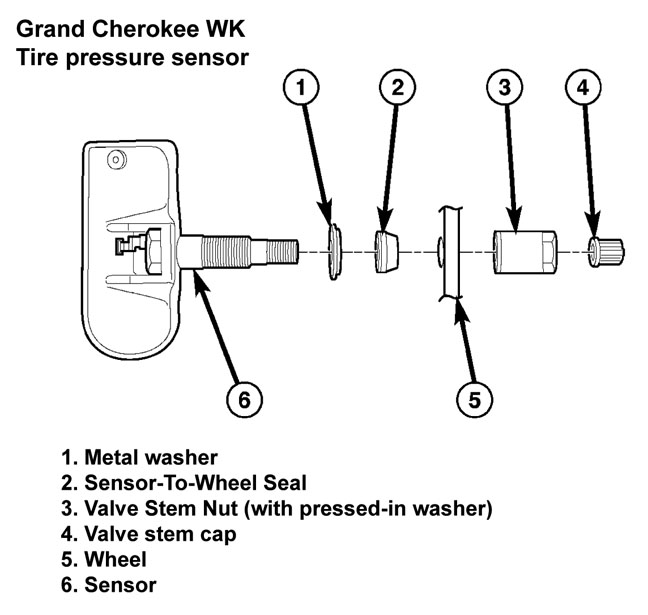
The valve stem caps and cores used are specifically designed for the tire pressure monitoring sensors. Although similar to standard valve stem caps and cores, they are different. The valve stem cap has a special seal inside to keep moisture and corrosion out. The valve stem core has a special nickel coating to protect from corrosion.
The battery operated tire pressure sensors lay dormant (Park Mode), then wake and start transmitting (Drive Mode) when the vehicle first reaches speeds over 20 mph (32 km/h). Once the wheels stop rotating for a period of approximately 20 minutes, the sensors shut down until again awaken. Although not transmitting as when in Drive Mode, while in Park Mode, the sensors still transmit approximately once every 13 hours to let the receiver know air pressure status at that time.
Using an RF signal, each sensor transmits tire pressure data approximately once every minute. Each sensor’s (transmitter) broadcast is uniquely coded so that the wireless control module (WCM) can monitor the state of each of the sensors on the four rotating road wheels. The WCM automatically learns and stores the sensor’s ID while driving after a sensor has been replaced. There is no formal retraining procedure necessary.
CAUTION 1: The use of tire sealants is strictly prohibited for vehicles equipped with the Tire Pressure Monitoring system. Tire sealants can clog tire pressure sensors.
CAUTION 2: Tire pressure sensor valve stem caps and cores are specially designed for the sensors. Due to risk of corrosion, do not use a standard valve stem cap or core in a tire pressure sensor in place of the original equipment style sensor cap and core.
CAUTION 3: Do not attempt to install a tire pressure sensor in an aftermarket wheel. Use tire pressure sensors in original style factory wheels only.
CAUTION 4: Any time a sensor is to be installed in a wheel, a new seal and washer must be installed on the stem to ensure air tight sealing.
NOTE: TPM thresholds have been established for the original tire size equipped on the vehicle. Use original size tires only to maintain system accuracy.
Part numbers in Red text are the latest revisions and what is recommended for replacement. Part numbers are current as of April, 2016. |
|||||||||||||||||||||||
| Description | Part # | ||||||||||||||||||||||
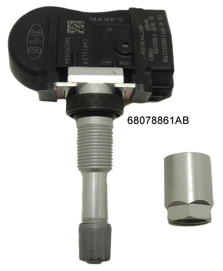
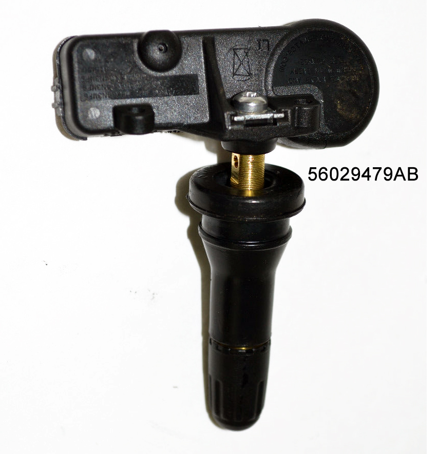
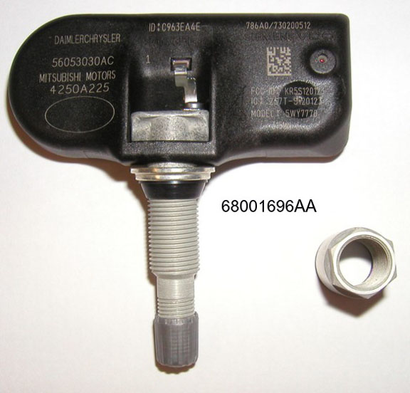
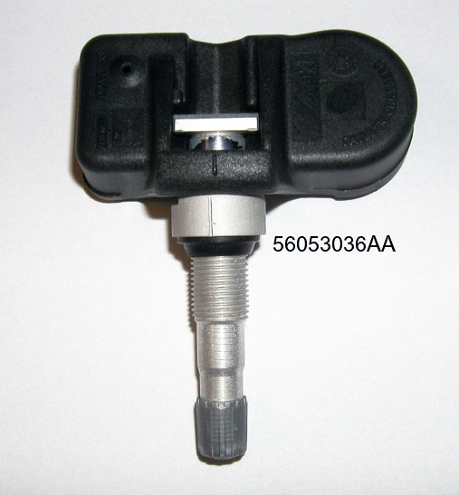
| Sensor – WK models | 2005-2006 (315MHz)68001696AB (includes 56053030AC sensor, nut and cap) superseded by 68078861AB (includes 56029479AB sensor, nut and cap) 2007 (except SRT8) (315MHz)56053036AA (includes sensor and cap)
2007 (SRT8) (315MHz)68001696AB (includes 56053030AC sensor, nut and cap)
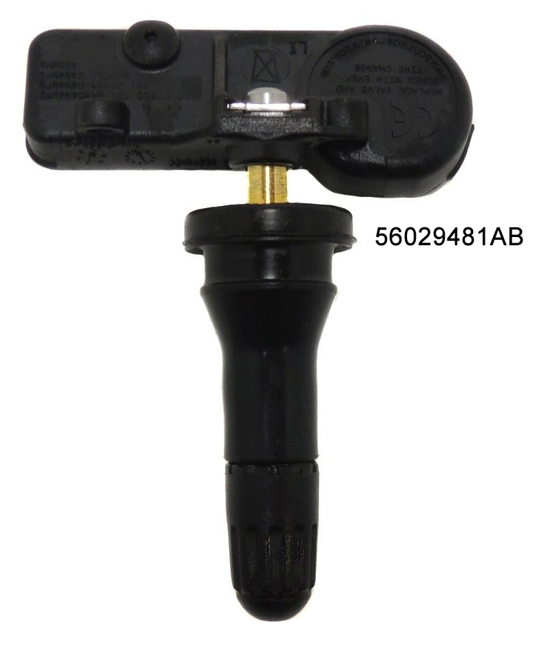
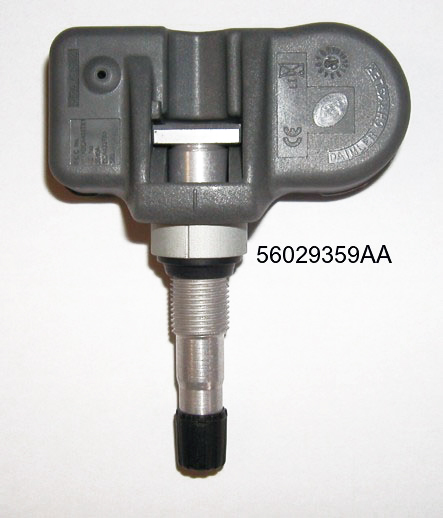
2008-2010 (433MHz)56029359AC (includes sensor and cap)
|
||||||||||||||||||||||
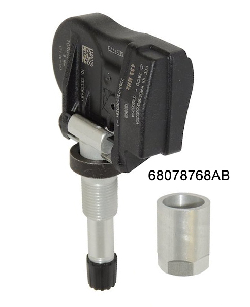
| Sensor – WH export models | 2005-2007 (433MHz)68001698AB (includes 56053031AD sensor and cap) superseded by: 68078768AB (includes sensor and cap) 2008-2010 56029359AC |
||||||||||||||||||||||
| Cap kit (5 caps and stems) | 68024258AA (2005-2007)
68023890AA (2008-2010) |
||||||||||||||||||||||
| Nut | 56053033AB (2005-2007)
56053037AB (2008-2010) |
||||||||||||||||||||||
|
|||||||||||||||||||||||

The “Tire Pressure Monitoring Indicator Lamp” will illuminate in the instrument cluster, and an audible chime will be activated when one or more tire pressures is low. The “Tire Pressure Monitoring Indicator Lamp” will flash on and off for ten seconds when a system fault is detected. The flash cycle will repeat every ten minutes or until the fault condition is removed and reset.
The base Tire Pressure Monitoring System consists of the following components:
- Receiver Module
- 4 (or 5*) Wheel Sensors
- Amber Colored Tire Pressure Monitoring Indicator Lamp
*A sensor is located in the spare wheel if the vehicle is equipped with a matching full size spare wheel and tire assembly.
Base system operation
The tire pressure monitoring system is designed to operate without loss of function for all types of standard tire constructions. (Function with different types of run flat tire constructions needs to be evaluated for each design). The wheel sensor shall monitor tire pressure, air temperature inside the tire, wheel acceleration and the sensor internal battery status for all four active road tires. The sensor will broadcast this information, along with a unique 32 bit ID, to a central receiver circuit located inside the WCM. The information received by the WCM will be decoded and stored in memory (RAM) in the WCM. If a “warning” or “fault” condition exists, the WCM will send a bus message request to illuminate the amber colored indicator lamp and to sound the chime.
If the WCM detects a warning or fault condition at ignition key “on” it will wait ten seconds +/- 10 % before sending the first request to illuminate the Indicator Lamp. This will assure that the display module has concluded its bulb check period. The display module will request a chime once per ignition cycle for each “warning” or “fault” condition detected. A “warning” or “fault” condition will remain enabled until the problem causing the condition is corrected and removed/reset.
The WCM shall continuously monitor for the receipt of tire pressure RF message transmissions from the wheel sensors during both the ignition key “on” and key “off” cycles. The wheel sensor ID’s and the location of each sensor (e.g. Tire 1, Tire 2 etc.) are stored in the WCM non-volatile memory during the initial Manufacturing Plant Process, or during a service procedure, as required. The recommended “placard pressure”, “low-pressure threshold” and “Hysteresis Pressure Values” for the tires installed on the vehicle, are stored in the WCM non-volatile memory during the initial Manufacturing Plant Process, or during a service procedure, as required.
The TPM System will continue to warn the driver of low tire pressure as long as the condition exists, and will not turn off the indicator lamp until the tire pressure is at or above the Low Pressure (lamp) OFF threshold (see placard table below). The system will automatically update and the TPM warning lamp will extinguish once the updated tire pressures have been received.
The tire pressure will vary with temperature by about 1 psi (6.9 kPa) for every 12°F (6.5°C). This means that when the outside temperature decreases, the tire pressure will decrease. Tire pressure should always be set based on cold inflation tire pressure (placard pressure). This is defined as the tire pressure after a vehicle has not been driven for more than 3 hours – and in outside ambient temperature. The tire pressure will also increase as the vehicle is driven – this is normal and there should be no adjustment for this increased pressure. For a system fault, the system will return to normal once the WCM receives a valid transmission from that sensor location.
Base system monitoring
This system will consist of Tire Pressure Monitoring (TPM) sensors attached to each wheel through the valve stem mounting hole, a Wireless Control Module (WCM) and a yellow TPM telltale lamp. A TPM sensor shall be installed in the spare wheel if the vehicle is equipped with a matching full size spare wheel and tire assembly.
Sensor learning mode
Each sensor’s (transmitter) broadcast is uniquely coded so that the wireless control module (WCM) can monitor the state of each of the sensors on the four rotating road wheels. The WCM can automatically learn and store the sensor’s ID while driving within 10 minutes continuously above 15 m.p.h. (24 Km/h) after a sensor has been replaced, the vehicle must be stationary for more than 20 minutes in order to initiate the learning sequence.
Spare tire sensor programming
On vehicles equipped with a Tire Pressure Monitoring System (TPMS), when the spare tire pressure sensor is replaced with a new pressure sensor, a diagnostic scan tool MUST be used to run a routine that will program the new pressure sensor ID into the Wireless Control Module (WCM), commonly referred to as the Sentry Key Remote Entry Module (SKREEM). Please copy the ID number off of the new pressure sensor before installing it into the spare tire. Then follow the programming steps outlined in the diagnostic scan tool for: ‘Learn Spare Tire Sensor ID’ under ‘Miscellaneous Functions’ for the ‘WCM/Wireless Control Module’ menu item as appropriate.
If replacing the WCM, the spare tire must be dismounted from its wheel to access and note the spare tire pressure sensor ID. Then follow the programming steps outlined in the diagnostic scan tool for ‘Learn Spare Tire Sensor ID’ under ‘Miscellaneous Functions’ for the ‘WCM/Wireless Control Module’ menu item as appropriate. In addition, the placard pressure thresholds must be updated in the new WCM. Go to “Update Pressure Thresholds” under “Miscellaneous Functions” for the “WCM Wireless Control Module” and follow the procedure.
Transponder
Transponders located in three of the four wheel wells of the vehicle to provide the Wireless Control Module (WCM) located in the Sentry Key Remote Entry Module (SRKEEM) with the location of the tire pressure sensors on the vehicle. The transponders are located in the left front, right front and right rear wheel wells. A fourth transponder is not necessary in the remaining wheel well due to the process-of-elimination theory. Once the system knows the location of the first three sensors it assumes the location of the fourth tire pressure sensor is in the left rear tire.
Notes and cautions
NOTE 1: It is particularly important, for you to check the tire pressure in all of your tires regularly and to maintain the proper pressure.
NOTE 2: For vehicles with optional wheel/tire sizes and significantly different tire placard pressures, the placard pressure value and the low-pressure threshold value is re-programmable at your authorized dealer to accommodate the customer selected wheel/tire combinations recommended by DaimlerChrysler Corporation.
NOTE 3:
- The TPM system can inform the driver of a low tire pressure condition.
- The TPM system is not intended to replace normal tire care and maintenance, nor to provide warning of a tire failure or condition.
- The TPM system should not be used as a tire pressure gauge while adjusting your tire pressure.
| CAUTION! The TPM system has been optimized for the original equipment tires and wheels. TPM system pressures have been established for the tire size equipped on your vehicle. Undesirable system operation or sensor damage may result when using replacement equipment that is not of the same size, type, and/or style. After-market wheels can cause sensor damage. Do not use tire sealant from a can, or balance beads if your vehicle is equipped with a TPM system, as damage to the sensors may result.CAUTION! After inspecting or adjusting the tire pressure always reinstall the valve stem cap. This will prevent moisture and dirt from entering the valve stem, which could damage the wheel rim sensor. |
The “Tire Pressure Monitoring Indicator Lamp” will illuminate in the instrument cluster, and an audible chime will be activated when one or more tire pressures is low. The “Tire Pressure Monitoring Indicator Lamp” will flash on and off for ten seconds when a system fault is detected. The flash cycle will repeat every ten minutes or until the fault condition is removed and reset.
The Premium Tire Pressure Monitoring System consists of the following components:
- Receiver Module
- 4 (or 5*) Wheel Sensors
- 3 Wheel Sensor Trigger Modules
- Tire Pressure Monitoring System Display Messages in the EVIC
- Amber Colored Tire Pressure Monitoring Indicator Lamp
*A sensor is installed in the spare wheel if the vehicle is equipped with a matching full size spare wheel and tire assembly.
Premium system operation
The tire pressure monitoring system is designed to operate without loss of function for all types of standard tire constructions. (Function with different types of run flat tire constructions needs to be evaluated for each design). The wheel sensor shall monitor tire pressure, air temperature inside the tire, wheel acceleration and the sensor internal battery status for all four active road tires and the spare tire, if so equipped. The sensor will broadcast this information, along with a unique 32 bit ID, to a central receiver circuit located inside the WCM. The information received by the WCM will be decoded and stored in (RAM) memory in the WCM. The WCM will send bus messages to the re-configurable display module to display the pressures of the four active road tires in vehicle position. The spare tire pressure is monitored but it is not displayed.
If a “warning” or “fault” condition exists, the WCM will send a bus message request to display the text messages and, when required, illuminate the amber colored ISO Indicator Lamp. “Warnings” and “faults” are described in more detail below. If the WCM detects a warning or fault condition at ignition key “on” it will wait ten seconds +/- 10% before sending the first request to illuminate the Indicator Lamp and to display the text messages. This will assure that the display module has concluded its bulb check period. The display module will request a chime once per ignition cycle for each “warning” or “fault” condition detected. A “warning” or “fault” condition will remain enabled until the problem causing the condition is corrected and removed/reset.
The WCM shall continuously monitor for the receipt of tire pressure RF message transmissions from the wheel sensors during both the ignition key “on” and key “off” cycles. The wheel sensor ID’s and the location of each sensor (e.g. Left Front, Right Front etc.) are stored in the WCM non-volatile memory during the initial Manufacturing Plant Process, or during a service procedure, as required. The recommended “placard pressure”, “low-pressure threshold” and Hysteresis Pressure Values for the tires installed on the vehicle, are stored in the WCM non-volatile memory during the initial Manufacturing Plant Process, as described later in this document or during a service procedure as required.
The TPM System will continue to warn the driver of low tire pressure as long as the condition exists, and will not turn off the indicator lamp until the tire pressure is at or above the Low Pressure (lamp) OFF threshold (see placard table below). The system will automatically update and the TPM warning lamp will extinguish once the updated tire pressures have been received.
The tire pressure will vary with temperature by about 1 psi (6.9 kPa) for every 12°F (6.5°C). This means that when the outside temperature decreases, the tire pressure will decrease. Tire pressure should always be set based on cold inflation tire pressure (placard pressure). This is defined as the tire pressure after a vehicle has not been driven for more than 3 hours – and in outside ambient temperature. The tire pressure will also increase as the vehicle is driven – this is normal and there should be no adjustment for this increased pressure. For a system fault, the system will return to normal once the WCM receives a valid transmission from that sensor location.
Premium system monitoring
The operation and lamp/chime strategy for a premium tire pressure monitoring system (TPMS) is the same as the base TPMS, but the premium TPMS can display text messages and a graphic display of the tire pressure on the information cluster. If a low pressure condition is detected, in addition to a chime and the indicator lamp turning ON, a low pressure text message indicating which tire is low will be displayed in the instrument cluster for 3 seconds. This text message will be followed by a graphic display of the pressure value(s) with the low tire(s) flashing. Once pressure in the suspect tire raises above the Low Pressure (lamp) OFF Threshold, the lamp will go out and the system returns to normal within approximately two minutes time. If a system fault is detected, in addition to the flashing lamp, a “Service Tire Press.System” text message will be displayed in the instrument cluster, and the graphic display will have “- -” in place of the pressure value. The system will return to normal once the WCM receives a valid transmission from that sensor location.
A Premium Tire Pressure Monitoring System (TPMS) determines the location of the tire pressure sensors by using transponders located in three of the four wheel wells on the vehicle. A fourth transponder is not necessary in the remaining wheel well due to the process of elimination theory. Once the system knows the location of the first three sensors, it assumes the location of the fourth tire pressure sensor, and update the graphic display when necessary.
For both the premium and base TPMS, the recommended “Placard Pressure”, “Low-pressure Threshold” and “Hysteresis Pressure Values” for the tires installed on the vehicle, are stored in the WCM non-volatile memory during the initial Manufacturing Plant Process, or during a service procedure, as required. To determine the pressure thresholds for a vehicle, refer to the Tire Inflation Pressure (Placard) Label, and then apply the placard pressure to the following table. The Low Pressure OFF Threshold is defined as the Low Pressure ON Threshold plus the Hysteresis Pressure Value.
Sensor learning mode
Each sensor’s (transmitter) broadcast is uniquely coded so that the wireless control module (WCM) can monitor the state of each of the sensors on the four rotating road wheels. The WCM can automatically learn and store the sensor’s ID while driving within 10 minutes continuously above 15 m.p.h. (24 Km/h) after a sensor has been replaced, the vehicle must be stationary for more than 20 minutes in order to initiate the learning sequence.
Spare tire sensor programming
On vehicles equipped with a Tire Pressure Monitoring System (TPMS), when the spare tire pressure sensor is replaced with a new pressure sensor, a diagnostic scan tool MUST be used to run a routine that will program the new pressure sensor ID into the Wireless Control Module (WCM), commonly referred to as the Sentry Key Remote Entry Module (SKREEM). Please copy the ID number off of the new pressure sensor before installing it into the spare tire. Then follow the programming steps outlined in the diagnostic scan tool for: “Learn Spare Tire Sensor ID” under “Miscellaneous Functions” for the “WCM/Wireless Control Module” menu item as appropriate.
If replacing the WCM, the spare tire must be dismounted from its wheel to access and note the spare tire pressure sensor ID. Then follow the programming steps outlined in the diagnostic scan tool for “Learn Spare Tire Sensor ID” under “Miscellaneous Functions” for the “WCM/Wireless Control Module” menu item as appropriate. In addition, the placard pressure thresholds must be updated in the new WCM. Go to “Update Pressure Thresholds” under “Miscellaneous Functions” for the “WCM Wireless Control Module” and follow the procedure.
Transponder
Transponders located in three of the four wheel wells of the vehicle to provide the Wireless Control Module (WCM) located in the Sentry Key Remote Entry Module (SRKEEM) with the location of the tire pressure sensors on the vehicle. The transponders are located in the left front, right front and right rear wheel wells. A fourth transponder is not necessary in the remaining wheel well due to the process-of-elimination theory. Once the system knows the location of the first three sensors it assumes the location of the fourth tire pressure sensor is in the left rear tire.
Notes and cautions
NOTE 1: For vehicles with optional wheel/tire sizes and significantly different tire placard pressures, the placard pressure value and the low-pressure threshold value is re-programmable at your authorized dealer to accommodate the customer selected wheel/tire combinations recommended by DaimlerChrysler Corporation.
NOTE 2: It is particularly important, for you to check the tire pressure in all of your tires regularly and to maintain the proper pressure.
NOTE 3:
- The TPM system can inform the driver of a low tire pressure condition.
- The TPM system is not intended to replace normal tire care and maintenance, nor to provide warning of a tire failure or condition.
- The TPM system should not be used as a tire pressure gauge while adjusting your tire pressure.
Warning messages
Tire Pressure Monitor System “warnings” will cause a text message to be displayed, an audible chime to sound and the “Tire Pressure Indicator Lamp” to illuminate. The audible chime will occur once every ignition cycle for each “warning” detected. The “Tire Pressure Indicator Lamp” will illuminate continuously (solid) and shall remain illuminated until the warning condition is removed/ reset.
NOTE: The Indicator Lamp will only illuminate for the four active road tires. A low spare tire pressure will not cause the Indicator Lamp to illuminate.
When the appropriate conditions exist, the Electronic Vehicle Information Center (EVIC) displays the following messages:
“LEFT FRONT”, “LEFT REAR”, “RIGHT FRONT”, “RIGHT REAR”, “SPARE LOW PRESSURE”
One or more of these messages will be displayed in the EVIC if a low tire pressure condition exists in one or more tires. Inspect all tires for proper inflation pressure, once the proper tire pressure has been set, the TPM system warning will reset automatically when the vehicle has been driven for at least 2 minutes at or above 15 mph (24 km/h).
“CHECK TPM SYSTEM” / “Service Tire Press.System”
See your authorized dealer when this message appears in the EVIC. This message indicates that a system fault condition has been detected.
| CAUTION! The TPM system has been optimized for the original equipment tires and wheels. TPM system pressures have been established for the tire size equipped on your vehicle. Undesirable system operation or sensor damage may result when using replacement equipment that is not of the same size, type, and/or style. After-market wheels can cause sensor damage. Do not use tire sealant from a can, or balance beads if your vehicle is equipped with a TPM system, as damage to the sensors may result.CAUTION! After inspecting or adjusting the tire pressure always reinstall the valve stem cap. This will prevent moisture and dirt from entering the valve stem, which could damage the wheel rim sensor. |
| TPM THRESHOLD PRESSURES | ||
| Placard Pressure (Cold) (PSI) | Low Pressure ON Threshold (PSI) | Low Pressure OFF Threshold (PSI) |
| 28 | 22 | 26 |
| 29 | 23 | 27 |
| 30 | 24 | 28 |
| 31 | 25 | 29 |
| 32 | 25 | 29 |
| 33 | 26 | 30 |
| 34 | 27 | 31 |
| 35 | 28 | 32 |
| 36 | 29 | 33 |
| 37 | 29 | 34 |
| 38 | 30 | 35 |
| 39 | 31 | 36 |
| 40 | 32 | 37 |
| 41 | 33 | 38 |
| 42 | 34 | 39 |
| 43 | 35 | 40 |
| 44 | 36 | 41 |
| 45 | 37 | 42 |
| 46 | 38 | 43 |
| 47 | 39 | 44 |
| 48 | 40 | 45 |
| 49 | 41 | 46 |
| 50 | 42 | 47 |
| 51 | 43 | 48 |
| 55 | 47 | 52 |
| 60 | 52 | 57 |
| 65 | 57 | 62 |
| 70 | 62 | 67 |
| 75 | 67 | 72 |
| 80 | 72 | 77 |